resources / teardown
SP-1 teardown
A photo-by-photo teardown of the Teenage Engineering SP-1 / Stem Player (nRF52840), down to safely disconnecting the LiPo battery - the manual power-cycle you need for firmware recovery. Every photo here is of a real unit, taken during my own teardown.
with thanks to
Tim Knapen (timknapen) - the SP-1's reverse-engineer and the author of its developer docs - who walked me through the tricky parts live and caught my mistakes in real time. If this guide is accurate, it is because of him.
Read this first
- The orange flex ribbon (FPC) is the one fragile, hard-to-replace part. No metal tools near it.
- The LiPo battery: never crush, puncture, or heat the pouch. A damaged cell can catch fire.
- Firmware: the app must link at 0x20000 - the TE bootloader owns everything below it. Writing below 0x20000 is the one truly unrecoverable, SWD-only brick.
- Go slow. Heat-and-pry in cycles, never brute force. If your unit doesn't match these photos, stop and ask before forcing anything.
Tools
- Hairdryer - NOT a heat gun (a heat gun melts the plastic and discolors the aluminum).
- Plastic spudger or guitar pick - no metal against the case or near the FPC.
- A toothpick - you need something soft for the FPC connector lever.
- Small Phillips screwdriver sized to the back-plate screws, if your unit has them.
- Plastic tweezers for the battery connector, and a soft surface to protect the aluminum.
A note on variants: TE built the SP-1 as a small run of prototypes / dev kits, and they vary. This unit has screws on the back plate; many are screwless and fully glued. If your seams or screws don't match these photos, photograph yours and ask the community before prying.
- 01
Pop the white plastic side piece
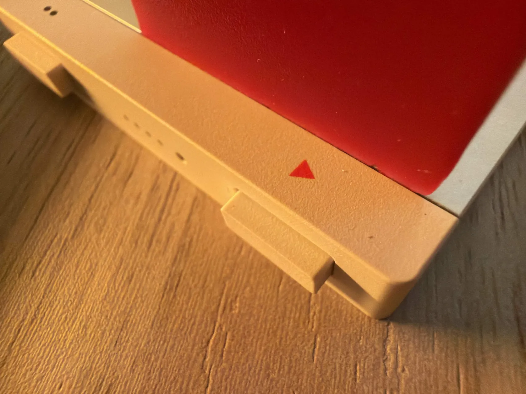
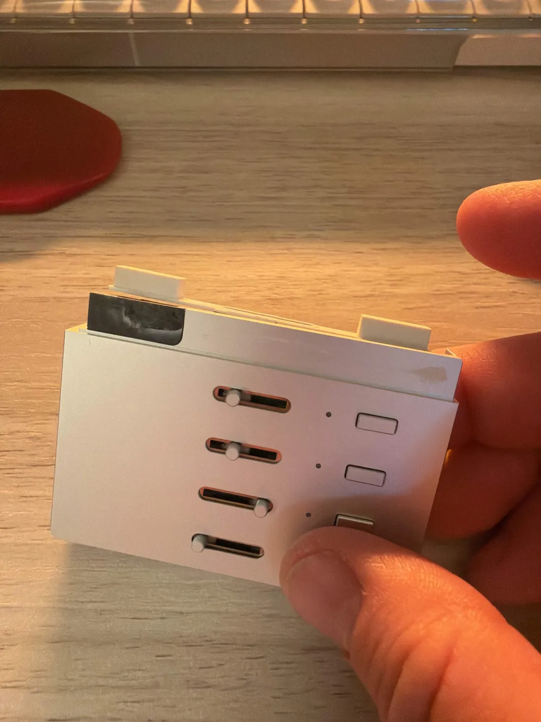
The entry point is the white plastic piece around the play/function buttons. It is held by adhesive in one spot, on the side opposite the buttons.
Warm that seam with the hairdryer for ~30 seconds, then gently lift the piece off with a plastic spudger - even pressure, in heat-and-pry cycles. Do not bend or yank it; the plastic deforms permanently. Several warm/cool cycles is normal.
- 02
Remove the back screw plate
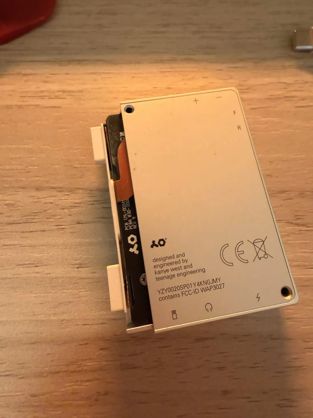
The back plate carries the regulatory marks, the TE logo, and the F/R + battery icons. On this unit it is held by screws plus a little light adhesive.
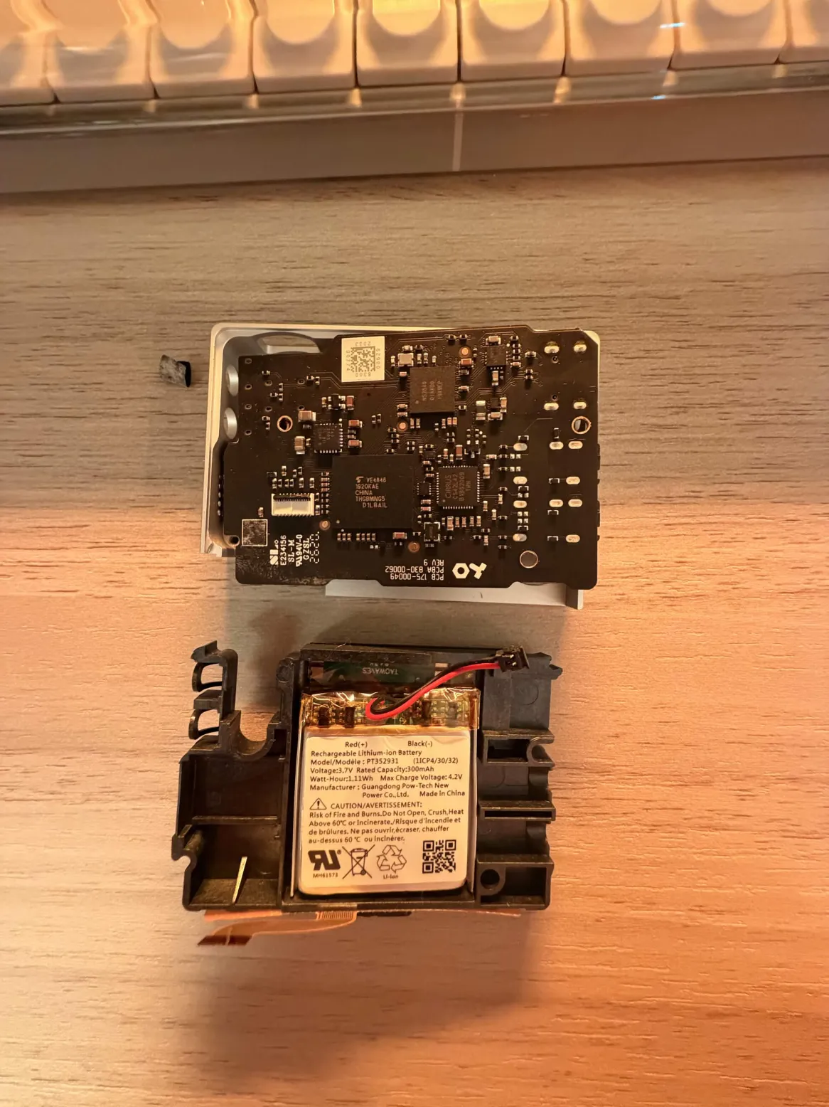
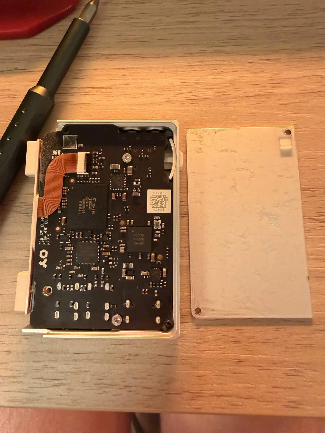
Back out every screw first (check the corners and the middle), then warm it and lift gently - once unscrewed it pops off with very little force, nothing like the side piece. Underneath is the main board: the nRF52840 SoC, the eMMC flash, and the orange FPC running into a white connector. The removed plate shows only glue residue; the battery is not on it.
- 03
Free the main board / front controls
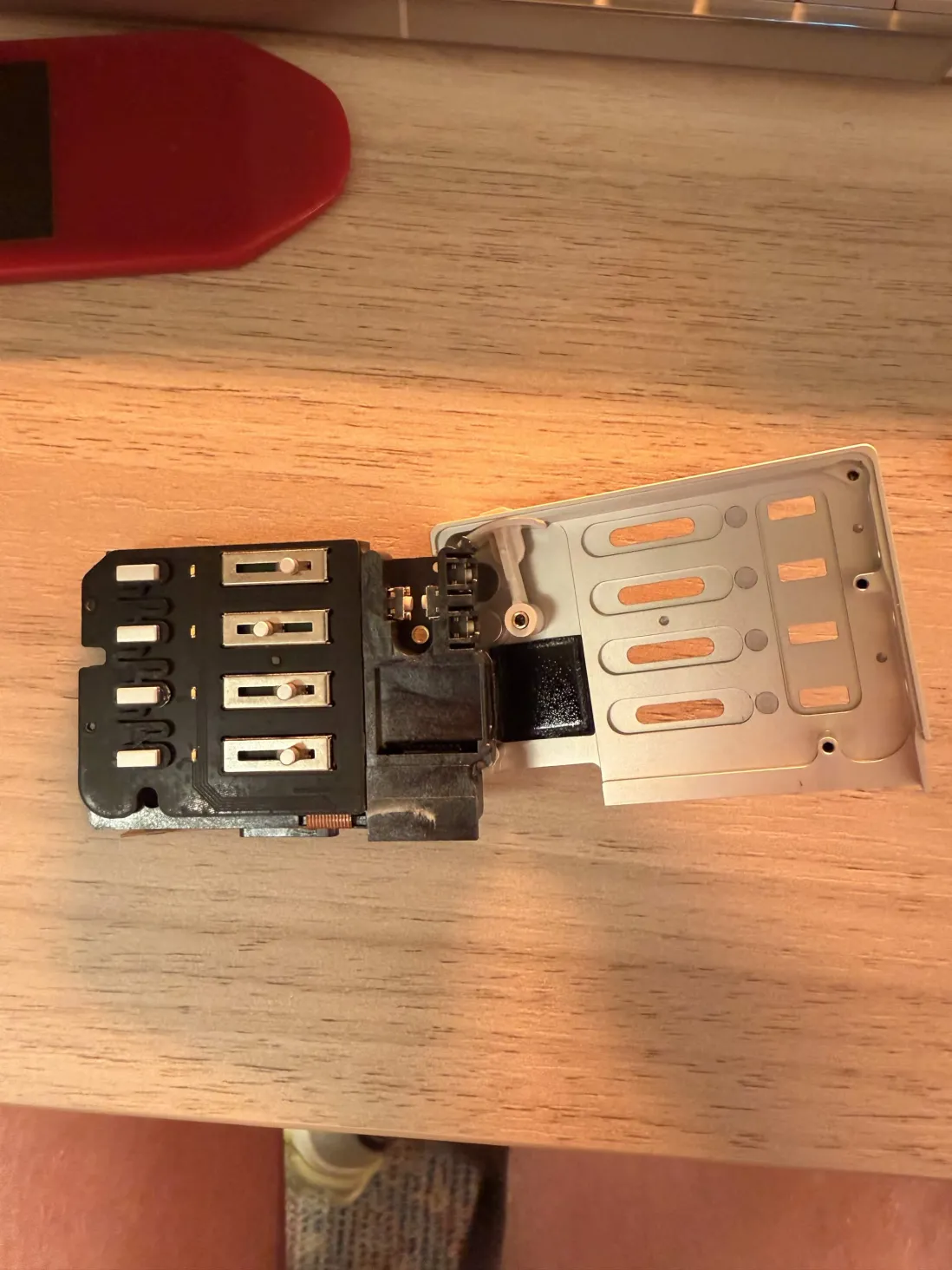
The main board plus the front-control assembly is one glued piece seated against the front of the case. Ease it up with the plastic spudger and a touch of warmth - gentle, even, from an edge.
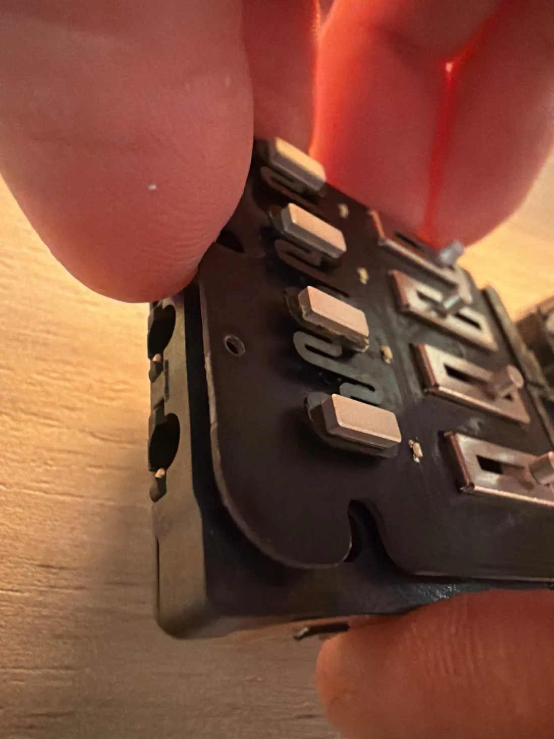
Keep the tool on the board edge or the plastic, never levering against the little chips or buttons - it is easy to snap a component off its pads here. The front controls (4 faders, buttons, LEDs) and the metal speaker bracket lift away together.
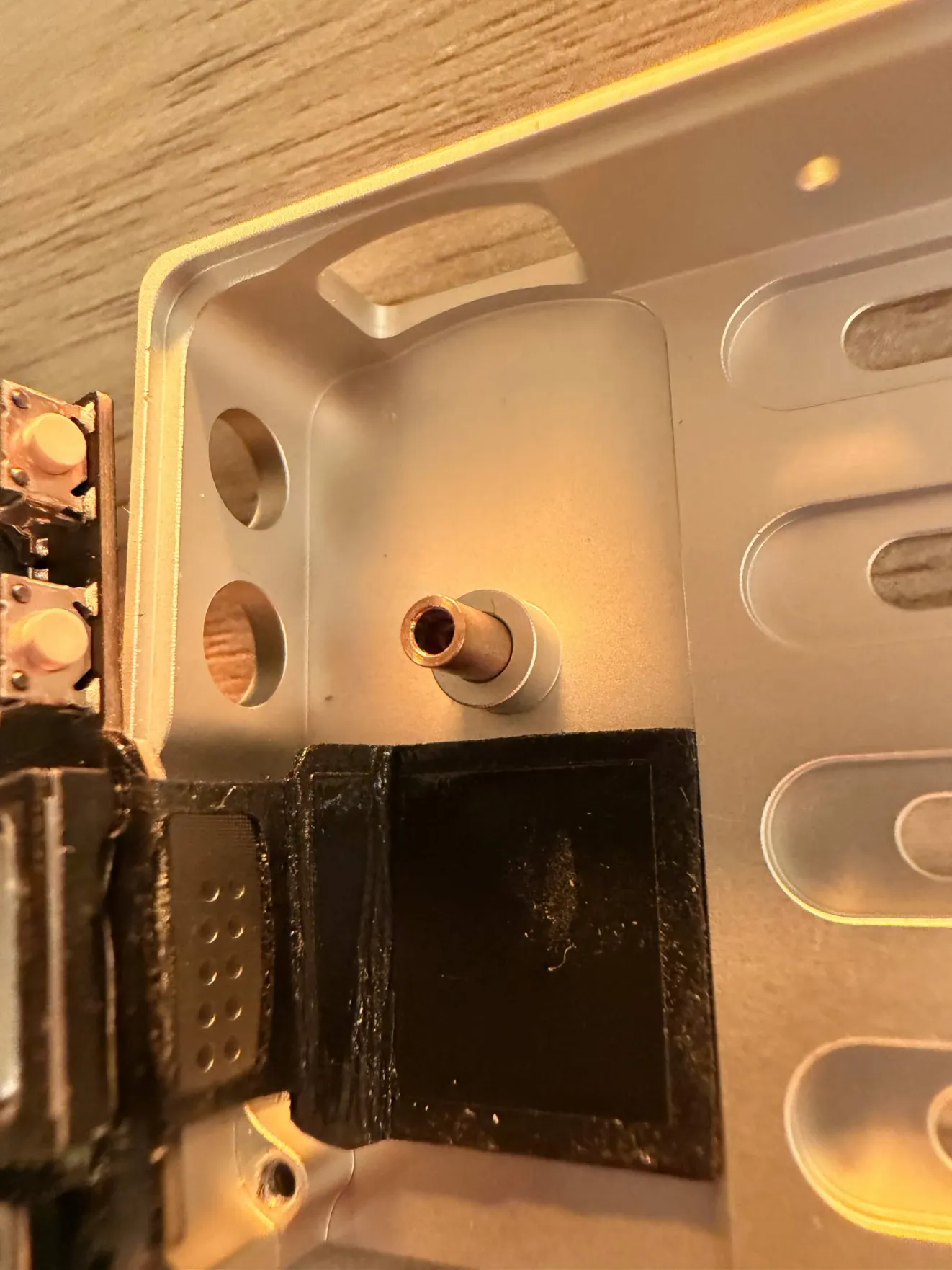
Inside the case you will see a black rubber gasket - the acoustic seal that joins the two halves around the speaker. Leave it intact (Tim's advice); it is part of how the speaker sounds.
don't lose the copper spacer
A small copper spacer sits in the case here and can drop right out - it is the bushing for the rocker (per Tim Knapen). Set it somewhere safe. On reassembly the rocker has to go back at exactly the right angle, with zero force.
- 04
Release the user-facing FPC ribbon
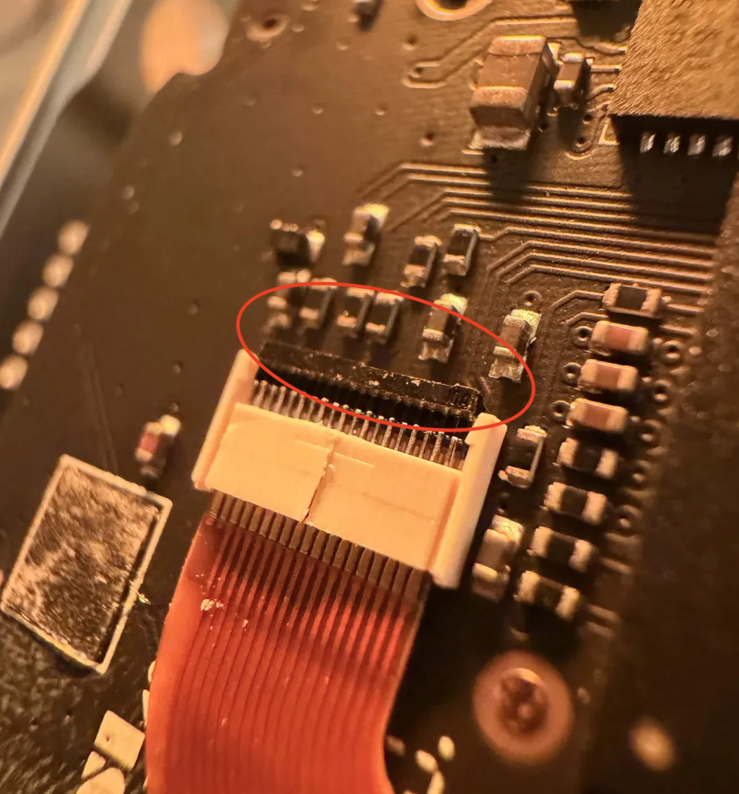
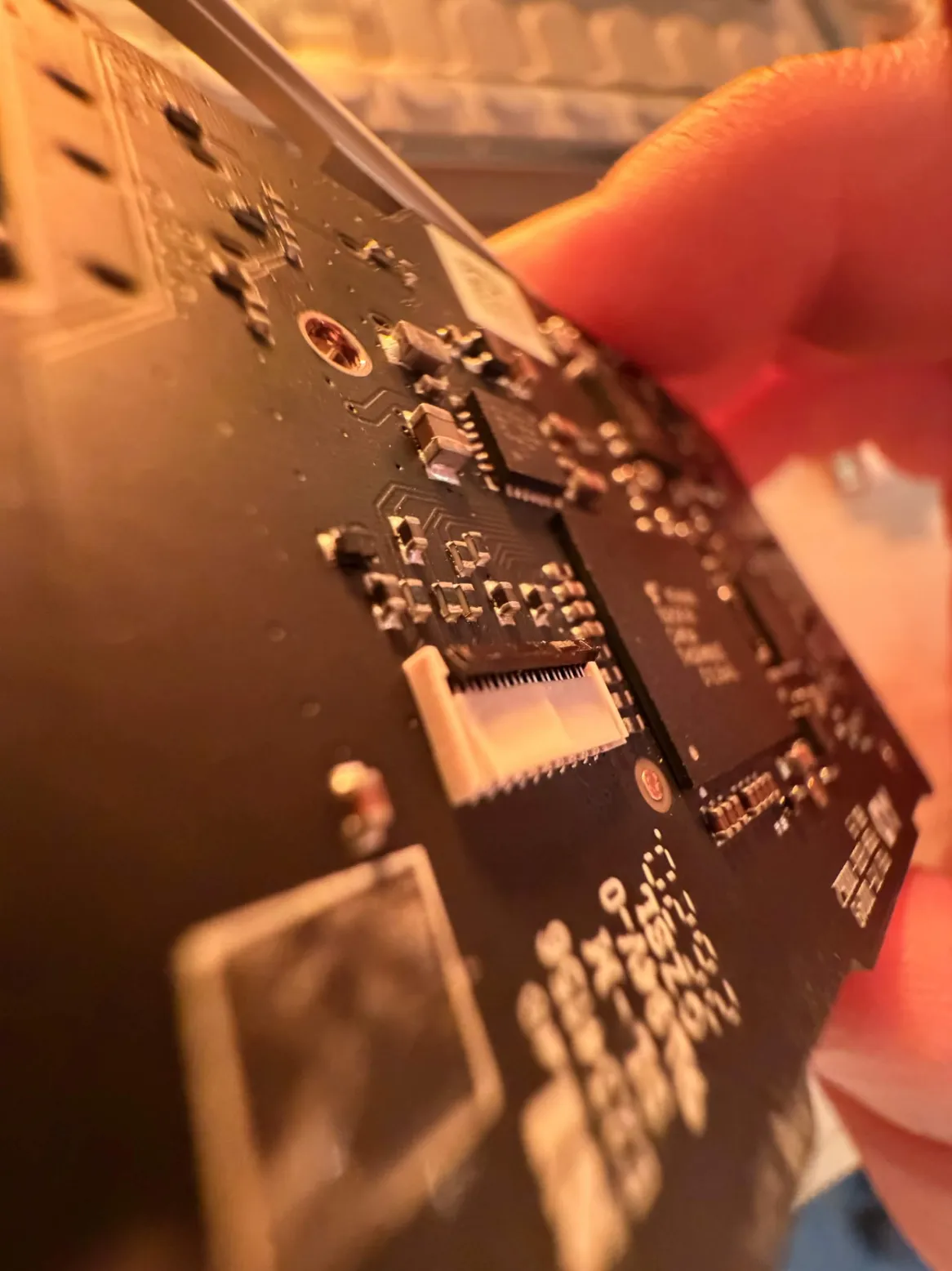
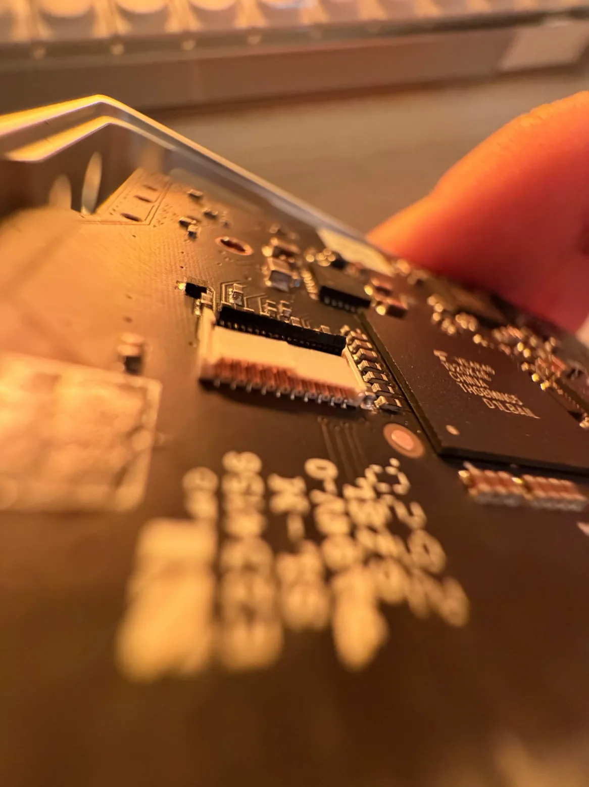
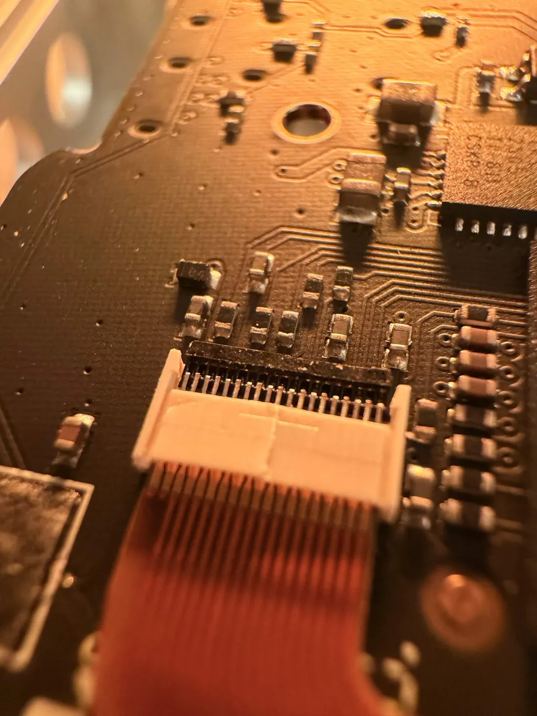
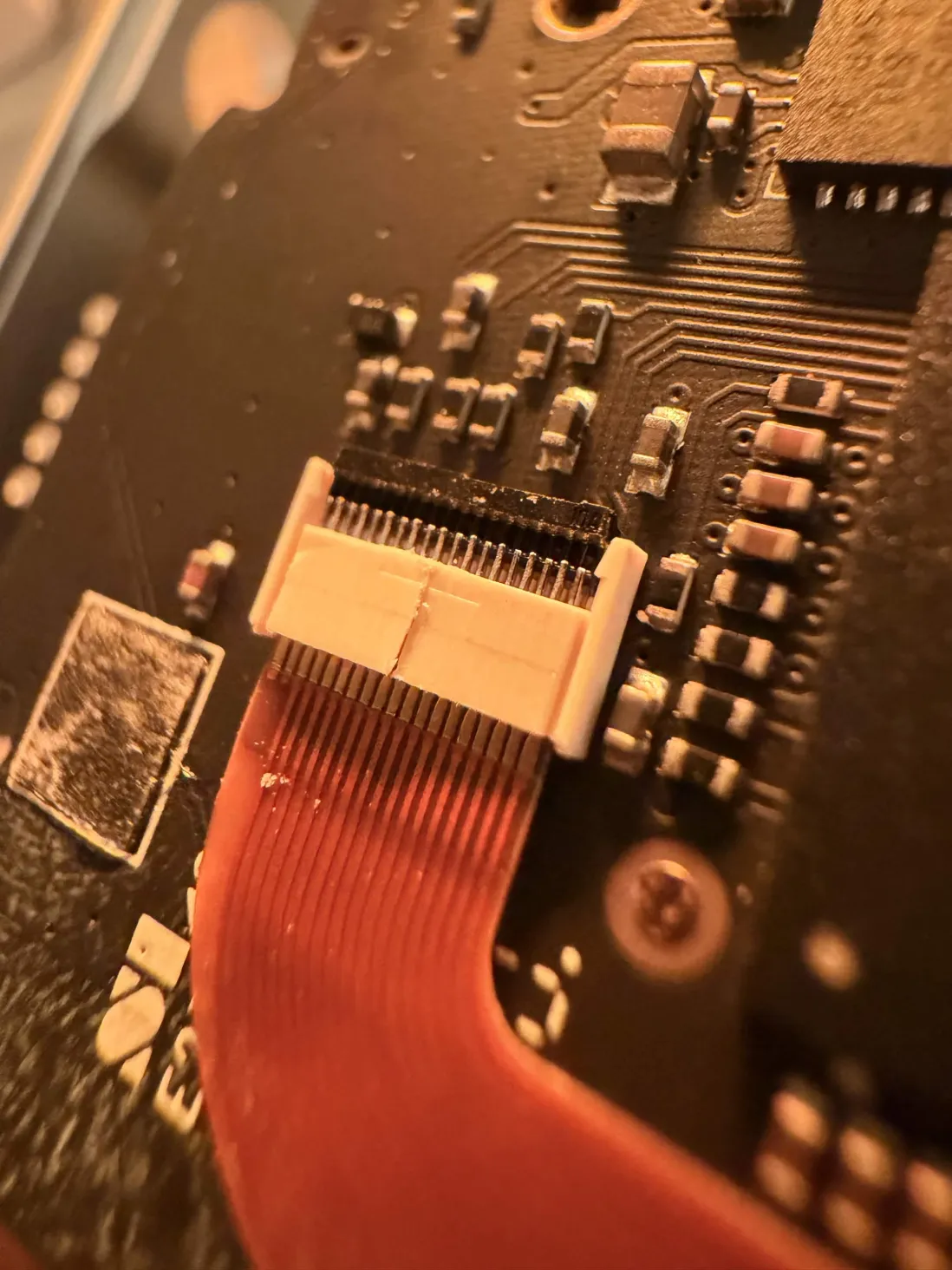
The orange ribbon plugs into a small flip-actuator connector (Omron XF3B). This is the part that trips everyone up - including me.
Lift the small BLACK lever (the actuator), NOT the cream-colored housing - lifting the cream housing shears the connector, and it tears like thin resin. The lever flips up from the back (the ribbon enters from the front). Use a toothpick with zero force: flip the lever up, then slide the ribbon out sideways in its own plane. Never pull it straight up.
the part i destroyed
Lift the BLACK lever, not the cream housing. The faders/pots and side LEDs are on separate connections; this ribbon carries the track LEDs and button power.
- 05
Flip the board - the battery is on the back
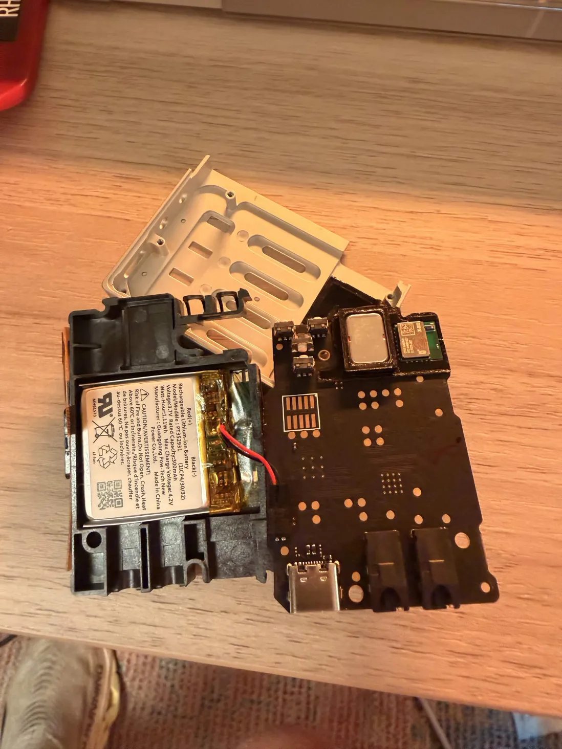
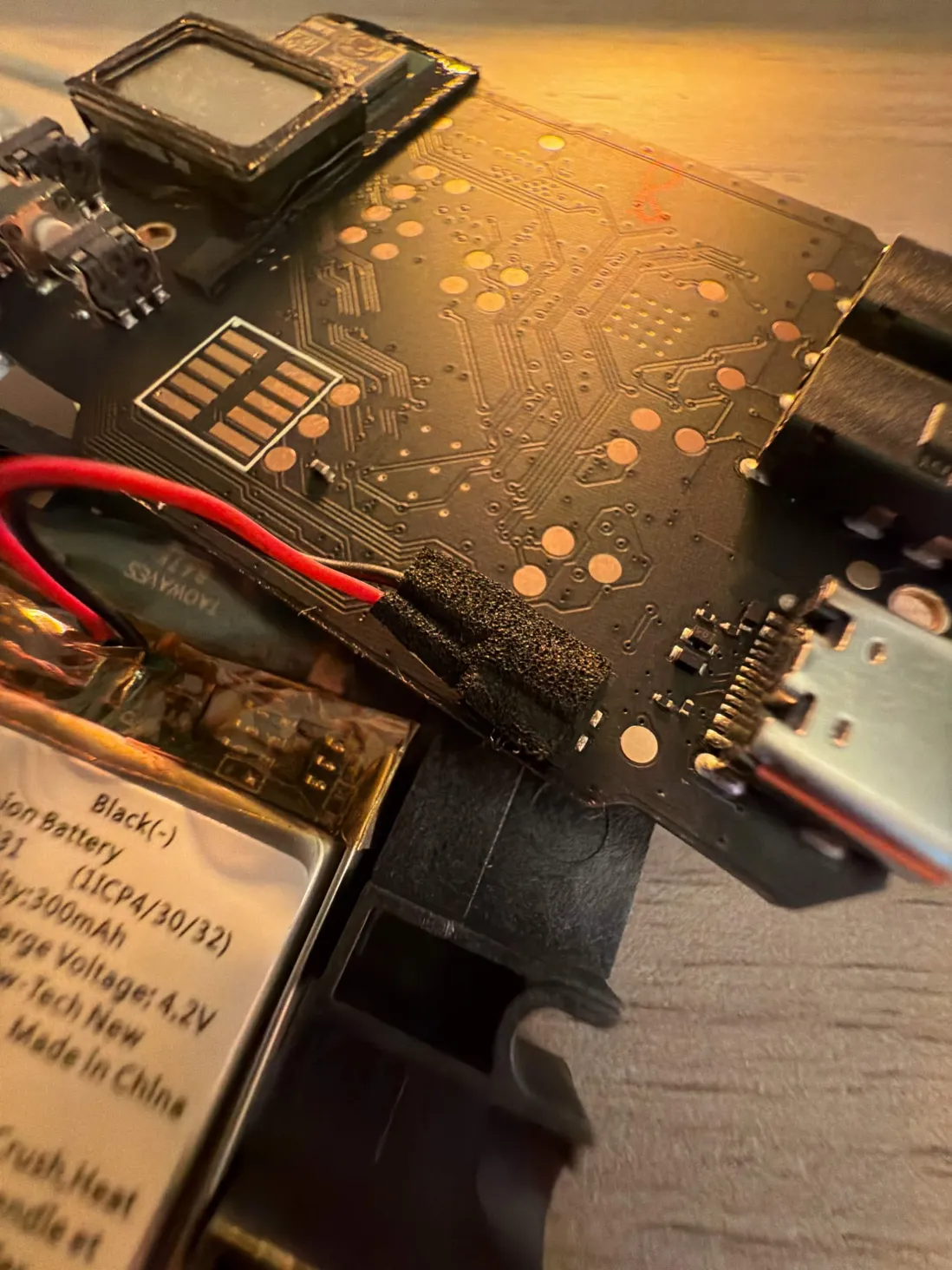
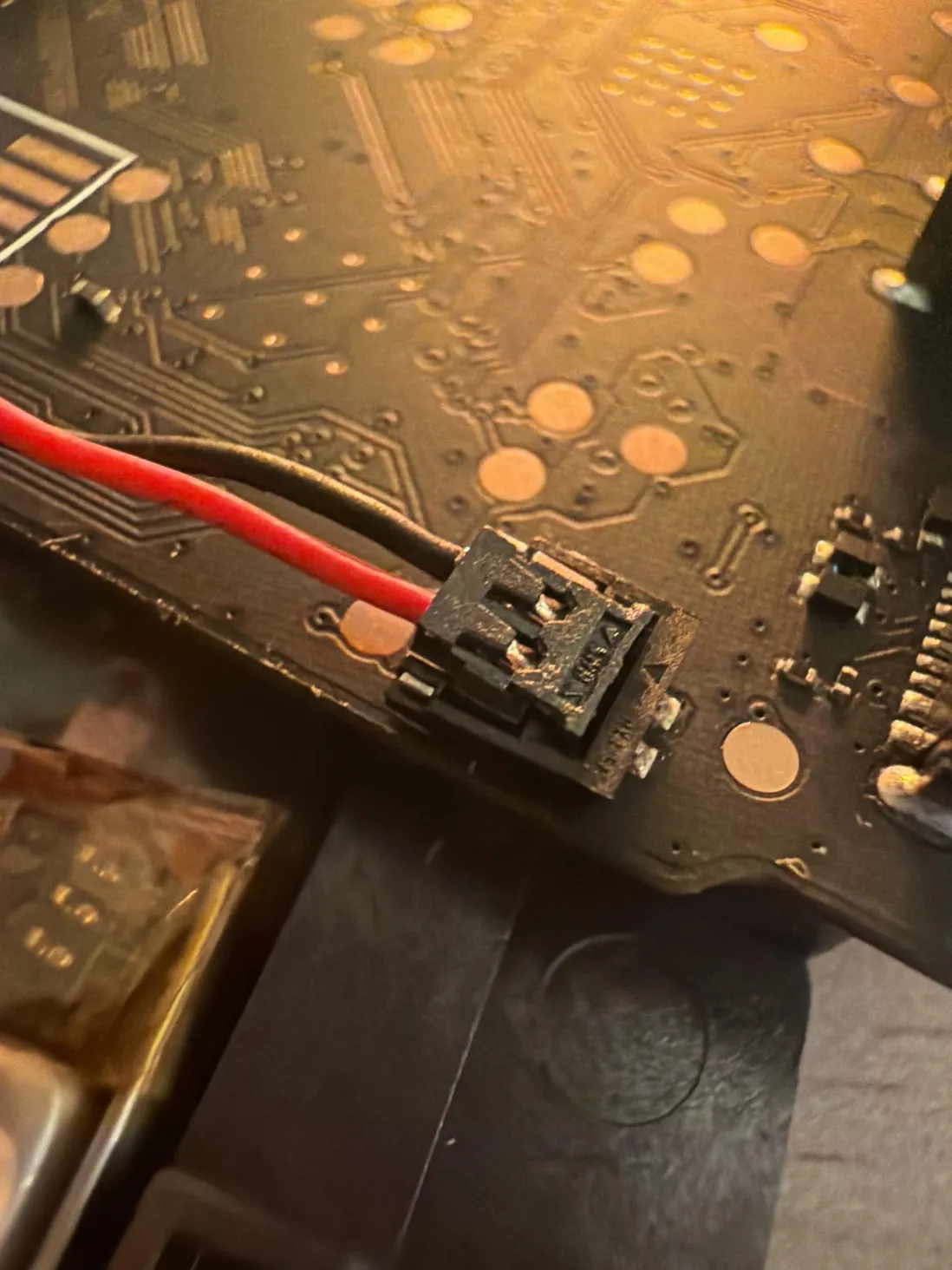
With the FPC free, flip the board over. The LiPo pouch is glued to the back of the main PCB (300 mAh, 3.7 V). Its red (+) / black (-) leads run to a connector hidden under a small black foam-tape flap.
The USB-C port and the Bluetooth module's metal shield can are also on this side.
- 06
Disconnect the battery
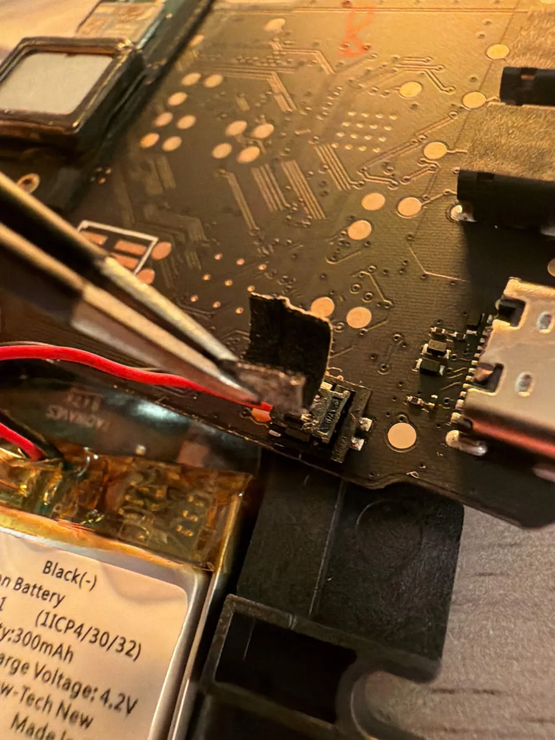
Peel back the foam tape covering the connection. It is a 2-pin connector, not soldered, so you just unplug it.
Grip the plastic connector housing (NOT the wires) and gently lift it straight UP off its header - a thin plastic pryer worked in from the front, light force. It releases vertically, not with a sideways pull. With metal tweezers, do not bridge the + and - pins; a direct LiPo short sparks.
That is it - the cell is disconnected and isolated. Unplug = power off, plug back in = power on, which is exactly the manual power-cycle you want for firmware recovery work.
Replacing a dead cell: some units arrived with a dead battery, and we previously listed a community swap here. We have pulled it. The SP-1's charger can push up to roughly 500 mA, while a smaller replacement cell's safe charge current can be far lower (a 350 mAh pack at 0.5C is only about 175 mA), so a casual swap can overcharge the new cell, which is a genuine fire risk. We do not have a verified charge-current spec for the SP-1, so we are not publishing a replacement procedure. If your cell is dead, treat it as a job for someone who can confirm the safe charge rate for any cell they fit.
Reassembly
- Reseat the FPC first - with the black lever UP, slide the ribbon back into the connector in its own plane and wiggle it in gently (no force), then push the lever back down with a soft tool like a toothpick. Don't bend or strain the flex; the only force it should ever feel is straight down on a button. A half-seated FPC is the #1 false “I bricked it”, so power it over USB (battery out) and test the buttons/LEDs before closing up - even a torn flex sometimes still makes contact when carefully reseated.
- Drop the copper rocker bushing back onto its post before the rocker goes in, then seat the rocker at exactly the right angle - no force. Tim's rule for the whole reassembly: no force anywhere.
- The old adhesive usually re-sticks on its own - no new glue needed. Refit the side piece, then the back plate (in that order; the back plate sits against the ribbon).
- Leave the black acoustic gasket and the speaker glue intact - they are part of the acoustic design.
Credits
All photos here are my own and free to reuse, but the knowledge is the community's and deserves the credit:
- Tim Knapen / timknapen / tkt1000 - the SP-1's reverse-engineer and dev-doc author, who corrected my mistakes live. The single most important source.
- the lines.co “TE Stem Player” thread - and its contributors (PedalsandChill, fishdog, murray, ItDitry, Duloz, and others) for the original teardown lore.
- dot-Justin's SP-1 knowledge base - and the lines-thread archive.
- solderless.engineering - for the firmware / stem tooling.